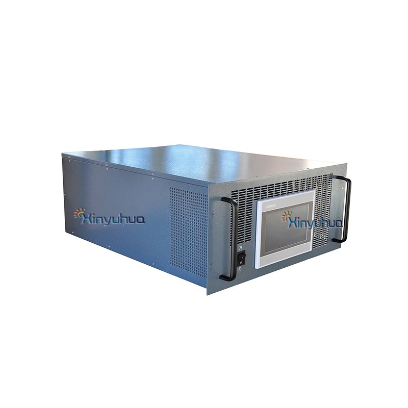
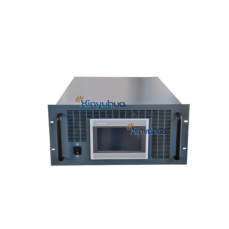
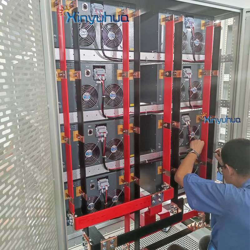
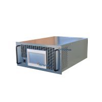
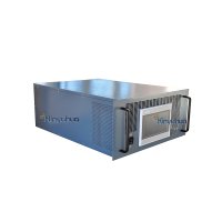
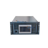
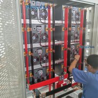
Bidirectional DCDC converter is applied to new energy, which operates in cooperation with battery, battery, DC bus, motor controller and motor to realize various operation conditions of new energy, energy recovery and prolong the service life of battery.
DC to DC Converter:
Working principle:
Bidirectional DCDC converter is applied to new energy, which operates in cooperation with battery, battery, DC bus, motor controller and motor to realize various operation conditions of new energy, energy recovery and prolong the service life of battery.

Function introduction:
1. Realize the two-way flow of energy, that is, it can charge from the battery side to the bus and charge the battery from the bus side
2. It has full-automatic protection functions such as overheating, overvoltage, overload and overcurrent
3. Original imported power devices shall be selected
4. The main control chip adopts microchip industrial MCU and full digital circuit design
5. All industrial chips are used, which can operate normally in cold, high temperature and humid environment.
6. Standard RS-232 communication, RS-485, GPRS, Ethernet and other communication modes can be selected to meet the needs of different occasions to the greatest extent
Technic Parameter:
| Model | 50K-1000kw DC-DC |
| Operation mode | Continuous work |
| Rated output power (KW) | 50-1000kw |
| High voltage side parameters | |
| Max.power( KW) | 50-1000kw |
| DC voltage range | DC 50V-850V |
| Current range | 0--±160A(3200A) |
| Voltage stabilizing accuracy | <0.1%F.S. |
| Current stabilizing accuracy | <0.1%F.S. |
| DC voltage ripple | <0.3%F.S. |
| Low voltage side parameters | |
| Max.power( KW) | 50 |
| DC voltage range | DC 0-800V |
| Current range | 0--±200A(4000A) |
| Voltage stabilizing accuracy | <0.1%F.S. |
| Current stabilizing accuracy | <0.1%F.S. |
| DC voltage ripple | <0.3%F.S. |
| Parallel No. | 20units |
| System | |
| System power supply | 1. AC 220 V (required when the low voltage side voltage is lower than 180V) |
| System power supply | 2. The low voltage side voltage is between 180v-750v |
| Noise | 65dB |
| Protect Class | IP21 |
| Allowable ambient temperature | -20℃~+45℃ |
| Cooling mode | Forced air cooling |
| Allowable relative humidity | 0~95% ( non-condensing ) |
| Max. allowable altitude | ≤2000m(derating over 2000m ) |
| Emergency stop | Yes (via emergency stop button) |
| Display and communication | |
| Display | External touch screen |
| Standard communication mode | Ethernet / RS232 (Modbus Protocol) |
| Size / weight | |
| Host size | W*L*H 482.6mm*600mm*222.2mm |
(Modbus TCPIP and Modbus RS485 )
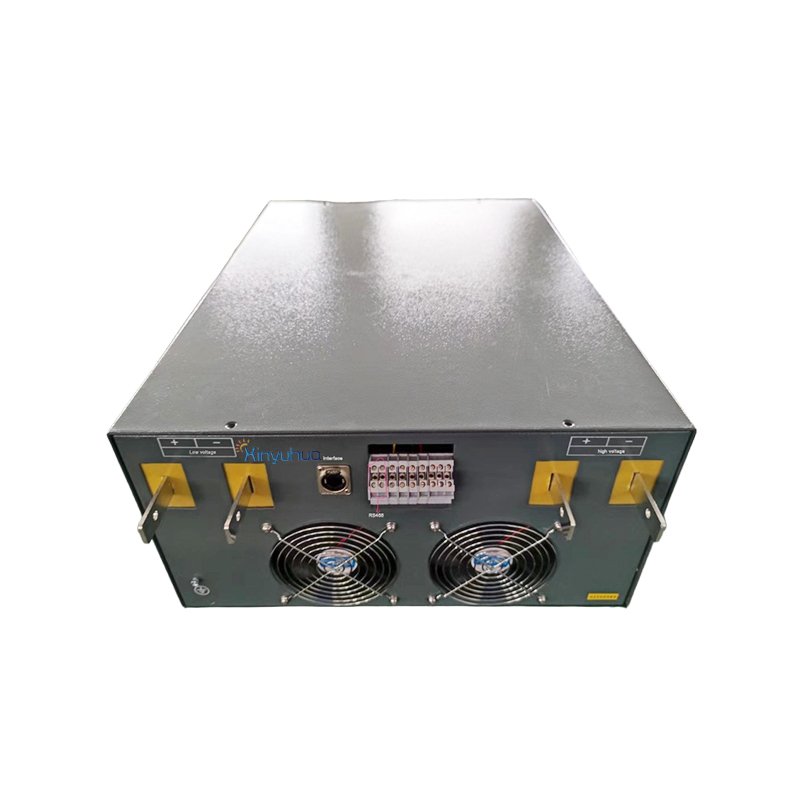
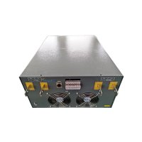
Equipment interface
The schematic picture is as follows

Interface introduction
The equipment interface has three interfaces: RS232 \ RS485 \ Ethernet;
1. RS232 is responsible for real-time communication with the lower computer control board for data acquisition;
2. Communication protocol internal customization;
3. RS485 interface is connected with remote equipment for remote control, and the equipment address can be set; Communication setting: 9600, N, 8,1; The communication protocol is standard Modbus protocol;
4. Ethernet interface is connected with remote equipment for remote control, and IP can be set; The communication protocol is standard modbustcpip protocol; The device address can be set3 、
5. Touch screen bit MODBUS server mode
6. To be filled in correctly
Local IP address 192.168.1.102
Local port number 3000
Remote IP address 192.168.1.100
Remote port number 3000
The following is a detailed explanation of the agreement
| No. | Variable name | R Read / write type | Register details | Register address (offset -1) | Variable units and decimal places |
| 1 | R | 16 bit unsigned binary | 1 | ||
| 2 | R | 16 bit unsigned binary | 2 | ||
| 3 | Ua | R | 16 bit unsigned binary | 3 | 1V |
| 4 | R | 16 bit unsigned binary | 4 | 1A | |
| 5 | Ub | R | 16 bit unsigned binary | 5 | 1V |
| 6 | R | 16 bit unsigned binary | 6 | 1A | |
| 7 | Uc | R | 16 bit unsigned binary | 7 | 1V |
| 8 | R | 16 bit unsigned binary | 8 | 1A | |
| 9 | R | 16 bit unsigned binary | 9 | 1V | |
| 10 | R | 16 bit unsigned binary | 10 | 1V | |
| 11 | R | 16 bit unsigned binary | 11 | 1V | |
| 12 | Freq2 | R | 16 bit unsigned binary | 12 | 0.1HZ |
| 13 | Udc bus | R | 16 bit unsigned binary | 13 | 1V |
| 14 | Udc_2 | R | 16 bit unsigned binary | 14 | 1V bias-32767 |
| 15 | Idc_1 | R | 16 bit unsigned binary | 15 | 1A bias-32767 |
| 16 | Udc_3 | R | 16 bit unsigned binary | 16 | 1V bias-32767 |
| 17 | R | 16 bit unsigned binary | 17 | ||
| 18 | R | 16 bit unsigned binary | 18 | ||
| 19 | R | 16 bit unsigned binary | 19 | 0.1KW | |
| 20 | R | 16 bit unsigned binary | 20 | ||
| 21 | R | 16 bit unsigned binary | 21 | 0=OFF 1=ON | |
| 22 | R | 16 bit unsigned binary | 22 | 3=Normal 2=DC power source | |
| 23 | R | 16 bit unsigned binary | 23 | Total charge 1*65535+ total charge 2 0.1kwh | |
| 24 | R | 16 bit unsigned binary | 24 | ||
| 25 | R | 16 bit unsigned binary | 25 | Total discharge 1*65535+ total discharge 2 0.1kwh | |
| 26 | R | 16 bit unsigned binary | 26 | ||
| 27 | ErrorFlag dc | R | 16 bit unsigned binary | 27 | |
| 28 | StartFlag dc | R | 16 bit unsigned binary | 28 | 0=OFF 1=ON |
| 29 | Mode Flag dc | R | 16 bit unsigned binary | 29 | |
| 30 | R | 16 bit unsigned binary | 30 | 2= constant voltage, constant current and constant power at low voltage side 6= constant voltage at high voltage side | |
| 31 | RW | 16 bit unsigned binary | 31 | ||
| 32 | RW | 16 bit unsigned binary | 32 | 1V | |
| 33 | RW | 16 bit unsigned binary | 33 | 1KW | |
| 34 | RW | 16 bit unsigned binary | 34 | 1KVAR | |
| 35 | RW | 16 bit unsigned binary | 35 | 3=Normal 2=DC power source | |
| 36 | RW | 16 bit unsigned binary | 36 | ||
| 37 | RW | 16 bit unsigned binary | 37 | ||
| 38 | RW | 16 bit unsigned binary | 38 | ||
| 39 | RW | 16 bit unsigned binary | 39 | ||
| 40 | RW | 16 bit unsigned binary | 40 | ||
| 41 | Start Stop dc | RW | 16 bit unsigned binary | 41 | |
| 42 | RW | 16 bit unsigned binary | 42 | 1V | |
| 43 | Udcset | RW | 16 bit unsigned binary | 43 | 1V bias-32767 |
| 44 | Idcset | RW | 16 bit unsigned binary | 44 | 1A |
| 45 | Pdcset | RW | 16 bit unsigned binary | 45 | 1KW |
| 46 | ModeFlagSetdc | RW | 16 bit unsigned binary | 46 | 2= constant voltage, constant current and constant power at low voltage side 6= constant voltage at high voltage side |
DC:DC Error Code Description
Error code description
| 1=DC overvoltage | Output overvoltage | |
| 2= DC short voltage | Input short voltage | |
| 10=over current | ||
| 14=over heat | ||
| 17= IGBT overcurrent | ||
| 19=system | ||
| 20=stop | ||
| 21= linkage |
Subscribe to our newsletter and be the first to know
about new productlaunches.
Add: No.220 Huayuan Road Jinan,China
Email:skyxo@126.com
Mobile/wechat/whatsapp:+86-186 5311 9810
Tel:+86-531-58539156
Copyright © Jinan Xinyuhua Energy Technology Co., Ltd. All Rights Reserved. Powered By HiCheng
